1. Design Goal
The goal was to design a pressure vessel to hold 50-60 cc of fluid at 700 psig. An o-ring seal, threaded connection, and NPT port must be included in the design.
2. Analysis and Background
In order to evaluate the circumferential stresses on a cylindrical pressure vessel, the following equations were used.
For thin-walled vessels, [1]-[3] apply.
Hoop stress: ![]() [1]
[1]
Axial stress: ![]() [2]
[2]
Radial stress: ![]() [3]
[3]
For thick-walled vessels, the thin-walled relationships are no longer valid, and shear stresses between the inner and outer radii must be considered. The thick-walled vessel relationships for Po=0 are given below in [4]-[6].
Hoop stress:  [4]
[4]
Axial stress: ![]() [5]
[5]
Radial stress:  [6]
[6]
where P is pressure, r is radius, and t is thickness.
In determining the minimum dimensions necessary to prevent each mode of failure, the thick-walled analysis is redundant.
The selection of fasteners for this design required the consideration of several criteria and modes of failure. First, the fastener must be self-locking, meaning that the screw requires external effort to cause rotation. The fastener must also be rated to withstand nominal stresses within the screw body. Stresses are concentrated at the fillet and at the start of the threads. In order to properly withstand tensile loads, bolts must be preloaded. It is common for fasteners to fail during preloading or during installation, when threads are likely to be stripped and they must withstand the maximum load allowed by the setup. The equations for each of the potential failure modes are listed below.
Self-locking ![]() [7]
[7]
Maximum nominal shear stress ![]() [8]
[8]
Axial stress ![]() [9]
[9]
Bearing stress ![]() [10]
[10]
Bending stress ![]() [11]
[11]
Transverse shear stress ![]() [12]
[12]
Preload torque ![]() [13]
[13]
where f is the coefficient of friction, l is the lead angle, t is shear stress, T is torque, d is diameter, s is stress, F is axial force, n is the number of engaged threads, p is pressure, K is the torque coefficient, and Fi is the preload force.
3. Design
3.1 Material Selection
In selecting the material for the pressure vessel, metal rods noted for their machinability and strength were chosen. Aluminum, copper, brass, bronze, and steel were all considered in the selection process, and steel was chosen for its relatively low price per foot. Of the steel options, 1214 carbon steel provided the highest strength, greatest machinability, and largest diameter range for the lowest cost.
3.2 Vessel Thickness
Initial analysis using the thin-wall equations for a pressurized cylinder indicated that the vessel required a thickness of only 0.02625 in, but the minimum value is impractical as a realizable dimension. In particular, the minimum fastener head size determined the thickness of the vessel wall. Because the heads of the bolt are intended to distribute the carried load over an extended surface area, placing the bolts with their heads outside the wall of the vessel cylinder reduces their effectiveness.
3.3 Fastener Selection
As in material selection, the merits and costs of each fastener variety was considered in the purchase of the fasteners. Screws were preferable to bolts because they can be used in threaded holes without securing with a nut. Within the screws, cap screws were selected over machine screws due to their graded strengths. Because the cost differential was minimal between finely and coarsely threaded screws, the finest variety was chosen to ensure self-locking. Additionally, the selected length of the fastener correlates to twice the width of the cap to prevent the separation of the cap from the main body. Our fastener was a 1.5 inch long, ¼” x 20 screw. Again, the negligible difference in cost between the Grade 5 and Grade 8 screws suggested that the Grade 8 cap screws were a more prudent choice for the prevention of tension, torsion, or shear failure.
3.4 O-Ring Selection
Using the Parker o-ring selection guide, the o-ring ID, OD, and groove dimensions were determined for the known plug diameter. Because wider o-rings are generally preferable to their thinner counterparts, the ideal o-ring would be the widest possible selection allowed by the shaft dimensions. Due to insufficient information during the ordering process, the prototype o-ring is sufficient, but not ideal.
3.5 Plug Design/O-Ring Placement
The cap and plug design was chosen for its machinability and o-ring placement. With the help of the machine shop experts, it was determined that the tools required to create the o-ring groove on the plug would be more accessible than those needed for the cap groove. Because the merits of both configurations are comparable, the advice of the machinist was used as the determining factor in cap design. While including the plug adds an extra step to the machining process, the benefits of the design outweigh the increased cost of production. Having the O-ring on the plug makes the pressure vessel much easier to assemble because the plug can just be inserted into the pressure vessel and screwed in.
3.6 NPT Connection Placement
The ¼” NPT connection was placed on the cap to improve the usability. Since all of the connections were on the upper face of the pressure vessel, we had a flat surface on the bottom to rest the pressure vessel on, and we could fill the pressure vessel without the cap on. This made it easy to assemble; we put the pressure vessel on the table, filled it up with water, and installed the cap.
3.7 Bill of Materials (Items Used)
|
ITEM |
DESCRIPTION |
QTY |
P/N |
MANUFACTURER |
PRICE |
|
1 |
12” Easy-to-Machine 1215 Carbon Steel bar, 3” diameter with tolerance of -0.004”, 12” in length |
1 |
4416T291 |
McMASTER |
$62.08 |
|
2 |
Buna-N O-Ring, size 220, 1 3/8” inner diameter, 1/8” thick (cross section), pkg of 100 |
1 |
9452K41 |
McMASTER |
$8.12 |
|
3 |
Grade 8 Alloy Steel Hex Head Cap Screw Zinc Yellow Plated, 1/4″-20 Threaded, 1.5″ Length, Fully Threaded, pkg of 25 |
1 |
92620A546 |
McMASTER |
$10.28 |
|
Total Spent |
$88.48 |
||||
Additional Items Considered
|
ITEM |
DESCRIPTION |
QTY |
P/N |
MANUFACTURER |
PRICE |
|
1 |
12” Multipurpose Aluminum Alloy 6061 bar, 3” diameter with tolerance of +/-0.024”, 12” in length |
1 |
8974K821 |
McMASTER |
$47.25 |
|
2 |
Buna-N O-Ring, size 028, 1 3/8” inner diameter, 1/8” thick (cross section), pkg of 100 |
1 |
9452K115 |
McMASTER |
$6.54 |
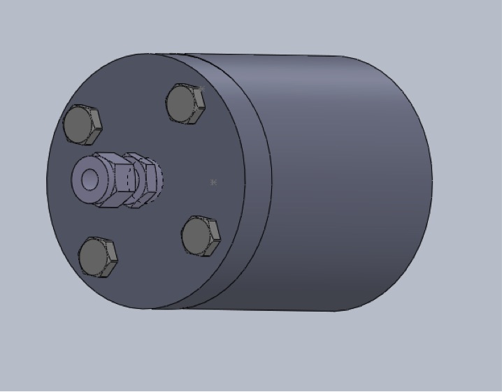
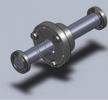
3D model of the pressure vessel exterior.
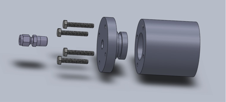
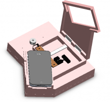
Exploded view of the pressure vessel.

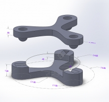
Figure 3. Drawing of vessel cap,
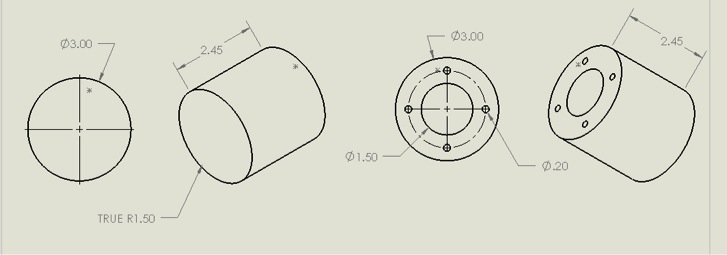
Figure 4. Drawing of vessel body.
4. Validation
The pressure vessel can fail in one of many possible ways. The different ways they can fail are listed below, along with the calculated safety factors. In the thick walled pressure vessel model, the hoop, radial, and longitudinal stresses can be obtained from equations [4]-[6]. These formulas yield the following results for a gauge pressure of 700 psi: (factors of safety determined using a yield strength of 60000 psi for the steel.)
Stress (maximum) |
Value (psi) |
Factor of Safety |
|
Axial |
1943.46 |
30.89 |
|
Radial |
1943.46 |
30.89 |
|
Hoop |
4576.92 |
13.11 |
|
Longitudinal |
2288.46 |
26.22 |
These stresses and factors of safety were calculated using the original design, not the “as built”. This was done because we finished our pressure vessel very close to the time it was due and had no time to redo all of these calculations. However, the calculations are still relevant because in every instance that we strayed from our original design, the factor of safety was either unaffected or increased.
Failure Modes:
– O-ring is rated at 1500 psi. Our pressure is 700 psi. Safety factor = 2.14.
Bolt failure
Force on the inside of the plug = pressure * area
= 700 lbf/in^2 * (pi*.75^2 in^2) = 1237 pounds of force on plug
Assume each bolt takes an equal load
1237 pounds / 4 bolts = 309.25 lbf per bolt
Bolt is rated at 150000 psi
Pitch diameter of bolt = .2175 inches
Max force bolt can take = 150000 lbf / in^2 * pi/4 * (.2175 in)^2 = 5573.14 lbf
Factor of safety = 18.02
Threads strip out of the pressure vessel
Steel yield strength = 60000 psi
Assume shear strength = ⅔ * yield strength = 40000 psi
Force = 309.25 lbf
Surface area = 1.5 in * pi * (.2175 in) = 1.0249 in
Actual shear stress on the steel = 301.724 psi
Factor of safety = 40000 / 301.724 = 132.57
NPT connection piece fails
Connection is rated for 4000 psi (Swagelok document on Bb)
Our pressure = 700 psi
Factor of safety = 4000/700 = 5.71
Threads fail at NPT connection
As per Dr. Simmons’ advice, we’ll model failure of the vessel threads as the failure of a standard 7/16” threaded connection, where the surface area is a 7/16” hole since the threads don’t go all the way through
Surface area = (.25 in) * pi * (.3911 in) = .3072 in^2
Force = 700 lbf / in^2 * pi/4 * (7/16 in)^2 = 105.23 lbf on the NPT connection
Shear stress on the hole = 105.23 lbf / .3072 in^2 = 342.58 psi
Factor of safety = 40000 psi / 342.58 psi = 116.76
After reviewing the different possible modes of failure, we expect that the system will fail via the O-ring because it has the lowest safety factor. We have 700 psi in our pressure vessel and the O-ring is rated for 1500 psi. Note that the rating may incorporate a safety factor into it, but we are unsure of that safety factor, so our safety factor is a conservative estimate.
5. Execution and Conclusions
5.1 Machining Process
First, the bar was cut in half along the cross section using a band saw. This was done because we had a 12-inch long bar of steel and it made machining easier. According to our design drawing specifications, 5.75 inches was needed to machine both the cap and the pressure vessel.
We then used the lathe to machine the male part of the cap. First, we faced off one of the cross sectional faces at 400 RPM. We then made 10 rough passes using the lathe power feed until the lathe blade reached 0.74 inches from the end, and then we manually took the blade to the final dimension. The chuck was operating at 450 RPM. This was repeated until the plug reached the proper 1.50 inch diameter.
To manufacture the O-ring groove, the blade of the lathe was placed at 0.5 inches from the end of the male part of the cap. The lathe (450RPM) was used to cut a groove 0.178 inches wide with a diameter of 1.497 inches. The cap was then turned around such that the cross section of the rough end of the cap is facing the lathe. We faced off the cap to even out the end, and then the cap was faced down at 450 RPM to the designed thickness of 0.5 inches.
For the main pressure vessel, we first faced-off the end at 400 RPM. To start boring, we put a control bit drill in halfway at 475 RPM. Next, we entered a size 17 US bit (0.173” diameter) 2.5 inches at 475 RPM lengthwise into the main pressure vessel. We used Tap Magic to keep the bit lubricated and constantly moved the drill bit in and out. Then we used a 2.5” long, 1” diameter drill bit at 200 RPM. Lastly, to bore out the last radial 0.25 inches, we used the lathe at 233 RPM, increasing the radius by steps of 0.025 inches.
In order to drill the holes in the cap and pressure vessel, we decided to clamp together the cap and pressure vessel so that we could drill the holes through both simultaneously, thus ensuring the holes would line up perfectly. The holes were positioned and center-drilled on the milling machine, and then drilled and tapped on the drill press.
5.2 Differences between planned and “as built”
During fabrication, a number of unforeseen obstacles arose that caused our “as built” pressure vessel to be slightly different from the original design.
- The cavity in our pressure vessel did not end up being perfectly cylindrically shaped. This was caused by the shape of the drill bit. The drill bit was elongated at the end, and this caused the cavity to be formed in the same way.
- The end of the pressure vessel is thicker than our design called for because when we cut the bar along its cross section, we left room for error. Afterwards, there was no need to saw off the extra material because it would only cause a decrease in the factor of safety.
- The o-ring groove was in a slightly altered location from what was intended. This was caused by a small miscalculation when deciding where to cut into the cap. In the end this was a very small deviation and should have negligible effects on the integrity of our design.
- The thickness of the o-ring was larger than originally planned. This is because we did not to properly size the o-rings before ordering them. It was resized to a standard ⅛” o-ring.
5.3 Conclusion
If we were to do this project again, we’d probably use a different material to start. The primary modes of failure were related to the strength of the O-ring and NPT connections, not the pressure vessel material. The steel we selected was very strong but took a long time to machine. We ended up spending several more hours in the shop than other groups, which made it harder to complete the project. We’d also do a better job planning our machine times so we’d finish earlier – we felt rushed near the end of the project.

