Background
The theory of kinematic constraint states that an object should be constrained by as many contact points as there are possible degrees of freedom to ensure that it has no degree of freedom. Kinematic couplings are useful in machine design because they are a cheap, precise, and robust manner of ensuring that two parts sit at the same relative position every time they meet.
Design
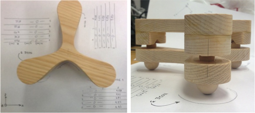
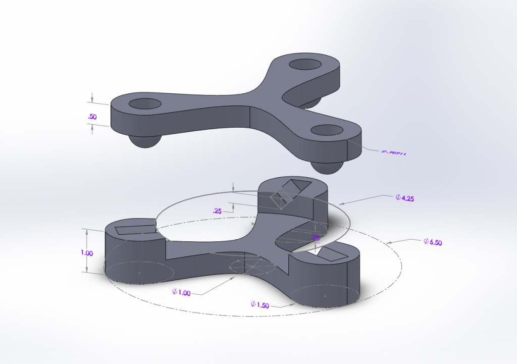
I chose to build a James Clerk Maxwell three-groove coupling where three V-grooves on one part are oriented towards the center and mate with three curved surfaces on the other part. My KC functions is a coaster holder that serves as an interesting center piece to an otherwise plain wooden table in my apartment. The KC sizing was done in function of the typical coaster size D=4”. Wood was chosen due to ease of manufacturing. The preload was merely the 50g weight of the top part of the KC. A 90o V-groove was chosen such that 1/4th of the ball would be sunk into the groove.
Manufacture
Router: The KC was manufactured using the MIT Hobby Shop’s router. Although the V-groove part of the KC was drawn as one solid part in Solidworks, it was necessary to fabricate it as two pieces with half thickness (i.e. the thickness of the wood) and then glue the V-groove ends to the curvy triangular piece. The thickness of wood was 0.6” instead of 0.5” like I had designed, but this fact did not require modifying the design, merely changing the MasterCAM file cut depth. In Solidworks I had cut-off a fragment of the spheres but in practice, I drilled cylindrical holes into the part and sunk the spheres into these holes. I learned that the router’s V-groove tool finishes off a line with a rounded end that I did not take into account in my CAD model. I was lucky that the rounded line just barely skimmed the edge of my part and remained invisible (as I hoped) when viewed in an assembled position. Assembly and Corrections: During design, I had incorrectly cut a ¼”-depth V-groove for a ¾” ball. Since the ball was too big for the groove, its two contact points were directly at the edge of the V-groove (rather than halfway along the groove’s planar surface) and, in high load applications, would cause points of high stress concentration. The stress concentrations, over time, would lead to failure in the part. This ball sizing error also affected the stability of my kinematic coupling which is why a slight V-groove misalignment became blatantly obvious with the ¾” balls. Folkers helped me fix this mistake: we flipped over the part, drilled new holes for D=½” balls and glued in these correctly sized spheres. Although not the original design intention, I think the new part looks artistic and evocative of an Oscar Niemeyer building (Niemeyer liked to show his buildings elevated off the ground).
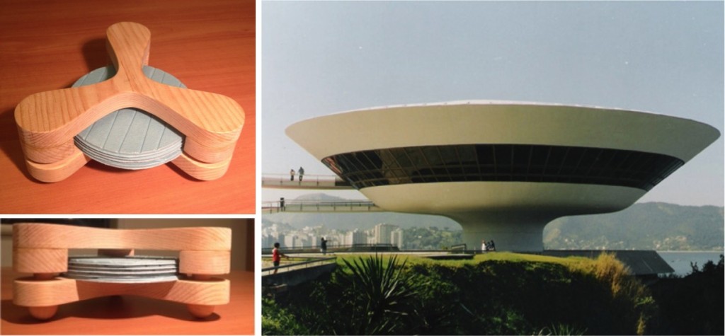
Limitations of the tools used to make my KC are (1) depth control of the router (probably not accurate to more than 2 decimal places) and (2) that glue + clamps + eyesight are not the best alignment tools. I can improve upon this alignment issue in the future by drawing lines that needed to be matched up on the outside of the KC, rather than trying to estimate what the inside of the part looked like after clamps obscured my view.
Analysis
The precision of the kinematic coupling was measured using calipers. It was not possible to utilize Abbe’s error because the geometry of the KC did not lend itself to x- and y-measurements. Due to its triangular shape, it would be difficult to stably attach the laser to the upper KC piece in such a manner that the laser would not interfere with the KC placement and balance, and such that the movement of the laser placement wouldn’t be a big source of error.
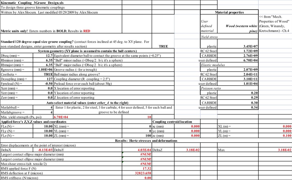
The KC design spreadsheet had predicted that my KC would have an x-, y- and z-displacement error of 8.27e-3 microns, 4.03e-4 microns, and 3.18e-2 microns, respectively. Since the KC has such a light load (50g), there was such little elastic deformation between two parts that no contact ellipses could be computed and the contact locations could essentially be considered to be points.
My experimental method of computing displacement error consisted of drawing a line joining the top and bottom part of the KC (considered the baseline). The two KC parts were assembled together five times and each time the displacement between the lines and the vertical distance between the parts was measured for each node. The average x- and y-displacement errors were 0±0 mm. The z-displacement error was 0.13±0.11mm. The experimental methodology was very prone to error given that it relied on my perception of when the calipers touched/slightly lifted up the two KC parts. With this methodology there was no way to measure the tiny variation in x- and y-position between the parts. Nevertheless, the experimental error measurements follow the same pattern as the theoretically predicted ones where the x- and y-errors are small and the z-error is almost two orders of magnitude larger. There is no necessity for a coaster holder to have better precision than even the max displacement error achieved experimentally, especially in the z-direction.

