Design Goal
The goal for this project was to finalize the tensioner shaft for a packaging machine drive. Given the constraint and dimension specifications of the instructor, we took fatigue, stress concentration, standard part availability and manufacturing considerations into account to finalize the design.
Problem Statement
The shaft assembly will apply a constant 100 lbf to tension the drive belt. The shaft is expected to turn at 100-300 RPM and will be in continuous operation except for maintenance and schedule shutdowns. It is expected that 2-3 will sell per month. The material is expected to be steel or stainless steel (prototype will be aluminum due to ease of machining).
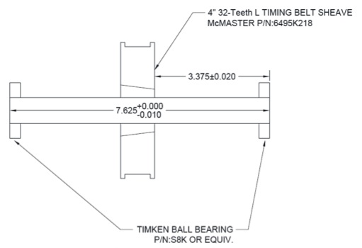
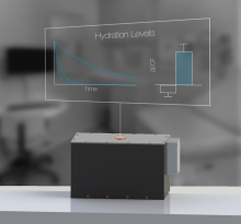
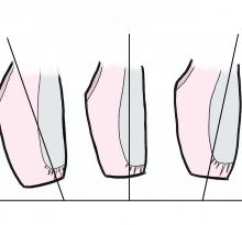
Figure 1. Given specifications for the machine driv
Description of Design Decisions
Based on the requirements presented, we must have a bearing at each end of the shaft and a pulley midway along its length. For such a design, we decided to put 4 steps on the shaft: 2 steps for the 2 bearings at each end, 1 step to be able to put the pulley and bushing on with ease, and 1 step for preventing the bushing from moving.
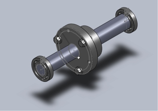
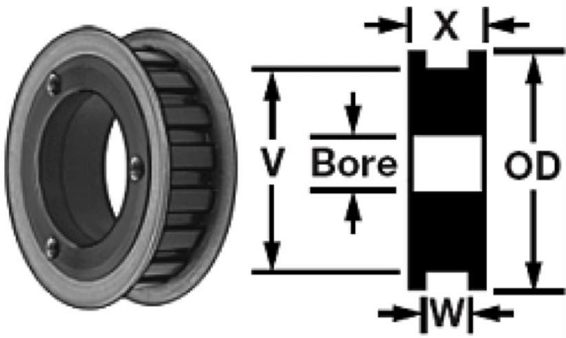
Figure 1 shows the schematic drawing of the manufactured shaft with implementation of bearings and pulley. Figure 2 shows the pulley, and Figure 3 shows one of the ball bearings that will be used in the assembly.
The diameters of the shaft were carefully chosen to meet the required specifications.
d1 = d5 = 0.7501 in. are the shaft diameters. d1 and d5 have to match the bore diameter of bearing which is 0.750 in. The diameter of the bearing surfaces was chosen to correspond with a k5 fit for the bearings, in accordance with Timken’s bearing design guide (Figure 13 in the Appendix).
d2 = 0.93 in. is the minimum recommended shoulder diameter of shaft according to the Timken design guide for an SK8 bearing is 0.93 in.
d3 = 0.9375 in. is the fixed bushing diameter. The bushing will connect the shaft and the pulley. A step is present on either side of the bushing; the higher step (d4) helps align the bushing laterally, while the lower step (d2) makes removal of the bushing easier.
d4 = 1 in. is the nominal diameter of shaft which is production size. The outer diameter was chosen because it is very close to the actual diameter of 1 in stock. This reduces the amount of time spent cutting the outermost diameter with the lathe.
r1, r2, r3 and r4 are differences between each diameters of the shaft.
We chose a bushing to attach the pulley on the shaft because the manufacturing bore size of pulley is too large for the shaft. We decided for the bore size of the bushing to be 0.9375 in which is between the minimum shoulder diameter of the shaft (0.93 in) and the nominal diameter of the stock shaft (1 in).
The length of the shaft was specified in the problem statement with appropriate tolerances.
In determining the design factor of safety for the weakest part of the shaft, it is important to note again that the shaft is to rotate at a constant RPM and experience a constant torque. We do not expect sudden changes in the torque or any situation that could threaten life, so a design factor of safety of 3 is used.
Our analysis (see page 10 for calculations) showed that the weakest part of the link is at d3. An estimated strength of 68 ksi (from an inexpensive steel, AISI 1020 cold drawn) gives a factor of safety well over the design value of 3. As we will see in the materials section, there are a variety of steels that meet or exceed this factor of safety.
The most important dimension is the diameter of the bearing surface. According to the manufacturer’s documentation, the bearing’s bore has a minimum and maximum tolerance of 0.7496 in. and 0.7500 in. respectively. Their documentation shows that a “k5” fit, defined as one of the tight fits, requires a minimum and maximum shaft tolerance of 0.7501 in. and 0.7504 in. respectively. See Figure 4 and 5 for a 3D model and detailed drawing of our shaft. As this is the typical case of a rotating inner ring, we believe that this type of fit is adequate for our purposes. The shaft is not expected to experience much thrust, as it is simply rotating at a relatively steady RPM. Therefore there is not a dire need for an extra tight fit; so long as it does not slide off on its own the fit should be adequate. We chose the manufacturer’s specification of a shaft with diameter of 0.7501” for a tight fit. A hydraulic press can be used to secure the bearing onto the shaft.
Detailed Part and Assembly Drawings
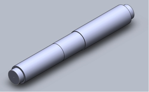
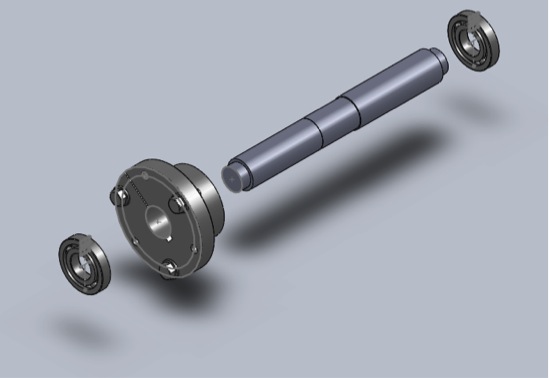
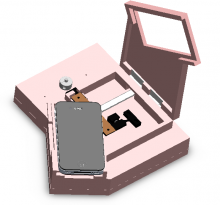
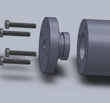
Figure 7. Exploded view of assembly of shaft, bearings and bushing
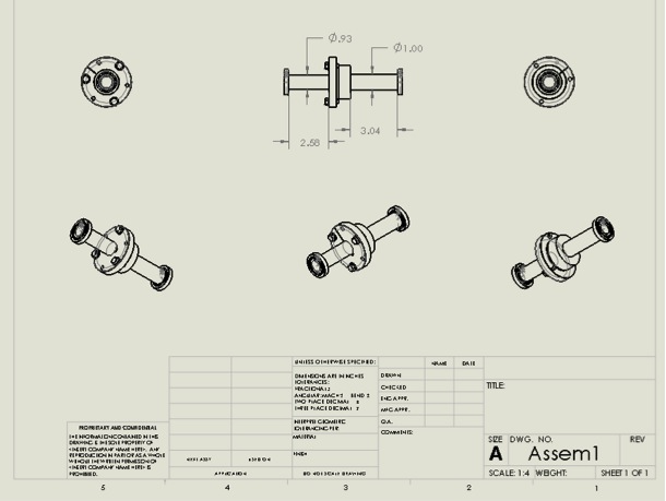
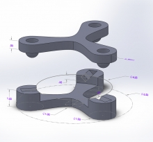
Figure 8. Technical Drawing of Assembly
Material and Treatment Selection
We began the material and treatment selection by compiling properties of several common steel and stainless steel alloys. Our goal was to select the cheapest material that would give us an appropriate factor of safety, using the formulas in the Fatigue Failure section. The results are below:
| Material | Price for a 3’ bar (McMaster-Carr, USD) | Ultimate Strength (psi) | Treatment | Calculated Factor of Safety |
| Stainless 304 | 44.65 | 73,200 | annealed | 9.552 |
| Stainless 416 | 44.74 | 74,700 | annealed | 9.774 |
| Stainless 410 | 47.32 | 65,000 | annealed | 8.505 |
| Stainless 303 | 54.6 | 89,900 | cold drawn annealed, room temperature | 11.763 |
| Stainless 316 | 55.91 | 89,900 | annealed | 11.763 |
| AISI 1117 | 21.73 | 86,300 | cold finished | 11.292 |
| AISI 1045 | 19.99 | 74,700 | cold drawn | 9.774 |
| AISI 1144 | 23.15 | 102,000 | as rolled | 13.346 |
Table 1. Material Cost, Strength, and Factor of Safety
We chose AISI 1045 because it was the cheapest material that met the specified safety factor.
Bill of Materials
| Component | Unit Cost (USD) | Quantity | Total Cost (USD) |
| 4” 32-Teeth L TIMING BELT SHEAVE – McMASTER P/N: 6495K218 | 35.89 | 1 | 35.89 |
| Quick-Disconnect (QD) Bushing Style SDS, 15/16” Bore, ¼” x 1/8” Keyway, McMASTER P/N: 6086K315 | 16.87 | 1 | 16.87 |
| Timken Ball Bearing, P/N: S8K | 12.92 | 2 | 25.84 |
| 1” Steel 1045 Rod, 3’ | 19.99 | 1/5 (can make 5 shafts with one piece) | 4.00 |
| TOTAL UNIT COST | 82.60 |
Fatigue Failure & Estimated Life
Our shaft was designed for an infinite life using the methods above. The bearing does have an expected lifetime, and its expected lifetime was calculated on the Timken design website.
We started with the initial assumption that the fillet is sharp. Therefore, we assumed bending and torsional stress concentration factors of 2.7 and 2.2 respectively (Table 7-1 of Shigley’s). Then we carried out the fatigue failure analysis described in Chapter 6. With assuming sharp fillet, we have rough estimated factor of safety values at the point of each step. This rough estimated factor of safety is assuming that the fillet of each step is sharper than the actual fillet for the prototype, in order to determine whether the rounded fillet is required for the final product. The rough estimated factor of safety confirmed that the shaft has enough buffer for the sharp edge. Then we re-substituted the values of diameter, step size, and rough estimated factor of safety to calculate actual stress concentration factor for both bending and torsion.
We then used the Goodman criterion fatigue failure analysis to calculate the actual factor of safety, and Goodman criterion fatigue failure analysis results in significantly higher factor of safety than rough estimates of factor of safety.
The following equations are equations used for the fatigue failure analysis
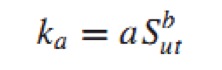
a = 2.7
Eq 1. Surface condition modification factor calculation
Full calculations and expanded equations can be seen in the full report pdf (link at the bottom of this page).
Given that we designed the shaft for infinite life, the bearing should fail before the shaft. The calculator on the Timken website suggested that given a load of 50 lb per bearing and a speed of 300 rpm, the adjusted life of the bearing for 13 million hours. This makes sense considering the extremely low load and RPM.
Our Prototype
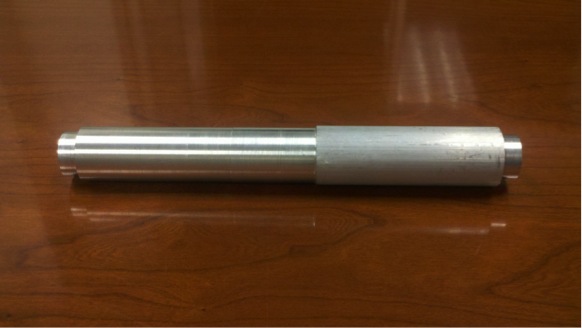
Figure 10. The machined shaft

Figure 11. The bearing attached to the shaft
Description of Manufacturing Approach for Prototype
The prototype was manufactured using a lathe in the machine shop. The stock was first cut to size by facing it until the bar was 7.625″ long. After the length was correct, the first bearing surface was manufactured by turning the diameter down to the appropriate size. Once the first bearing surface was manufactured, the bar was turned around in the lathe, and the other three diameters were turned. Our manufactured shaft is Figure 10, the end with the bearing is Figure 11, and the as-built drawing is Figure 12. Table 6 discusses the differences between our design and actual dimensions.
The shaft stock is not perfectly circular and this lack of symmetry can lead to fatigue. In the interest of time we could not prototype in this way but moving forward, it would be beneficial to do a quick pass of the lathe throughout the entire shaft to ensure that the whole part is circular and symmetric before moving forward and making measurements relative to outer surface of shaft.
Manufacturing Approach for Production
There are very few current orders for this component (2-3 per month), so the same manufacturing techniques can be used for production. If production volume were to increase, we recommend casting the rough outline of the component to reduce the time spent on the lathe. The casted components can be machined using a CNC lathe to ensure standardized quality control. Any manufacturers’ identifying information can be added with a laser.